
What is the K factor in sheet metal bending? This is the first question that comes to mind when you hear about metal sheet bending. Actually, when you look around you, you will find countless products made from bent sheet metal. In fact, sheet metal bending is one of the most critical manufacturing processes across many industries. It uses controlled pressure or force to bend a metal into a definite shape.
However, during bending, the thickness of the metal sheet changes continuously. Those changes can highly affect the final shape and dimension of the part. To resolve this issue, engineers use a concept known as the K factor. If you are new to this term, it might feel technical. To help you understand it, in this guide, I will explain everything about the k factor, its calculation, and factors affecting it. So let’s get started.
What Is the K Factor in Sheet Metal Bending?

The K factor is a ratio between the location of the neutral axis and the thickness of the sheet metal. It determines how the metal will behave during bending. As a result, manufacturers can produce bent parts with more accurate dimensions.
In other words, the K factor is the value that shows the position of the neutral axis. But before that, you have to understand what the neutral axis is. Actually, when a metal sheet is bent, a few changes take place. First of all, the outer side of the bend stretches and becomes slightly longer. At the same time, the inner side compresses and shortens slightly.
But between these two areas, there is a layer that shows no change in length. This is called the neutral axis. The K factor indicates where the neutral axis is located within the sheet metal thickness. Knowing its position is very important. Why? Suppose you want to know how much metal is needed before bending. You will definitely be confused about which length to use. The outer surface length? But it will become longer after bending. The inner surface length? It will become shorter when bent.
So the only option you have to use is the neutral axis. This is what remains nearly unchanged during bending. This makes it the most reliable reference point for bend calculations. So that’s actually the K factor that tells the location of the neutral axis in decimal form. If the K factor is 0, it means the neutral axis is located exactly at the inside surface. However, if the K factor of 0.5 means the neutral axis is located at the center of the material thickness.
Why Is the K Factor Important In Metal Sheet Bending?
As I said above, when a metal sheet is bent, its dimensions and shape change. These changes can cause serious problems later in the final product if you don’t consider them first. So that’s the K factor that helps the engineer predict the metal sheet’s behavior during bending. But that’s not all. Here are a few more reasons why the K factor is more critical.
- Improve Dimensional Accuracy: The first reason for using the K factor is that it improves the accuracy of bent parts. When a metal sheet is bent, its length changes. This means the final size of the part may be different from what was expected. But the K factor helps engineers predict these changes before bending takes place. Now they can calculate the correct flat-sheet size and make more precise bends.
- Reduce Material Waste: If the wrong sheet size is used, the finished part will be too large or too small. Right? In many cases, such parts cannot be used and must be thrown away. This directly increases material waste. But the K factor helps get the correct dimension of the final bend and reduces the material wastage.
- Manufacturing Efficiency: When manufacturers don’t know the K factor, they perform many bend tests. All this takes a lot of time and slows production. But the K factor helps make accurate calculations before production begins. This reduces trial and error, which improves production efficiency.
- Support CAD and CAM Systems: modern manufacturing now relies on software to design and produce sheet metal parts. This software always needs very accurate information to operate. The K factor provides this important information. When the correct K factor is fed into the software, it can generate more accurate designs.
How to Calculate K-factor: Steps & Formula You Must Know
Calculating the K-factor is all about finding the position of the neutral axis inside a sheet metal thickness. Right? In the real world, it is calculated through testing or from material data tables. But in these procedures as well, you must know how it is actually calculated. So let’s dive in and explore some steps involved in calculating the K factor.
Step 1: Understand the Information Needed
Before starting anything, you have to know what information will be needed during the K factor calculation. When you know that information, it will be easier to proceed. Generally, the first thing you will need is the total thickness of the sheet metal. The second one is the distance from the inside surface of the bend to the neutral axis. These measurements will help determine the location of the neutral axis within the material.
Step 2: Use the K-Factor Formula

Now you have two basic pieces of information from the initial step. The next part is to use those measurements in the formula. The K factor is usually calculated by dividing the distance to the neutral axis by the total material thickness. The formula for the K factor is the following.
K= t/T
Here:
K = K-factor
t = Distance from the inside surface to the neutral axis
T = Total sheet metal thickness
Step 3: Perform the Calculation
Now it comes to the most practical step: the actual calculation of the K factor. For this, you have to divide the distance to the neutral axis by the total metal sheet thickness. The answer will tell you where the neutral axis is located; that location is the K factor. Suppose you have a stainless steel sheet with a sheet thickness of 2 mm. You find that the neutral axis is located 0.8 mm from the inside surface. Now put the values in the above formula.
K-factor = 0.8 ÷ 2 = 0.4
It means the neutral axis is located 40% of the way through the material’s thickness, measured from the inside surface.
Step 4: Use the K-Factor Value in Bend Calculations
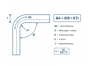
Once you get the K factor value, the job is not done here. You don’t only need the K value, but also have to implement it in real applications. Engineers use this value to calculate bend allowance, bend deduction, and flat pattern length. Bend allowance is the amount of material consumed by the bend.
The bend allowance equation is as follows:
BA=θ(R+KT)
Here:
BA = Bend Allowance
θ = Bend angle in radians
R = Inside bend radius
K = K factor
T = Material thickness
Factors That Affect the K Factor
Now you know how the K factor is actually calculated. Now remember that this K factor does not always remain the same for every bending operation. Several factors can highly influence the K factor value, even sometimes for the same material. So, before you start bending, here are a few factors that affect the K factor.
1- Material Type
The type of material you are bending is the first factor that changes the K factor. As you know, every material behaves differently during the bending. For example, there are two metal sheets with the same thickness. The first one is aluminum and the second is stainless steel. Aluminum is definitely very soft so that it will bend more easily. On the flip side, stainless steel is stronger and more durable, so it resists bending and deformation. In both cases, the position of the neutral axis will differ within the same metal sheet of the same thickness.
2- Material Thickness
Material thickness also affects the K-factor because thick and thin metal sheets do not behave the same way during bending. As I said above, when a sheet metal part is bent, the material stretches on the outside and compresses on the inside. So when a sheet is thin, it usually bends more easily. Why? Because there is less material resisting the bending force. On the other hand, the thick metal sheet contains more material that resists bending. Because of this difference, the position of the neutral axis may change, which directly changes the K factor.
3- Bend Radius
The bend radius is basically the curve formed on the inside of a bend. It is all about how sharp or smooth the bend is. The smaller the bend radius, the sharper the bend. However, if the bend radius is large, the bend will be smooth and regular. So, the bend radius is another factor that affects the K factor. How? Actually, the bend radius primarily affects the metal’s stretching and compression during bending. Now, if the bend radius is very small, the metal has to bend more sharply.
It means there will be greater stretching on the outer side and more compression on the inner side of the sheet. As a result, the neutral axis moves closer to the inside of the bend. When this position changes, the K factor will also change. Similarly, when the bend radius is larger, there are no severe changes inside and outside. In this case, the neutral axis stays closer to the middle of the material thickness. You can see that the position of the neutral axis has changed, which in turn changes the K factor.
4- Bending Method
The way you bend the metal sheet also affects the K factor. In general, there are three main bending methods. The first one is air bending, the second is bottom bending, and the third is coining. All of these methods use different amounts of force, which directly affect the neutral axis.
For example, if we talk about the air bending, the metal is not fully pressed into the die. As a result, a low amount of force is applied, which changes how internal compression and stretching occur. So the position of the neutral axis, and therefore the K-factor, will change. The same goes for coining and bottom bending: the metal is pressed tightly. This shifts the neutral axis somewhere else, which alters the K factor.
5- Tooling Design
For bending, manufacturers generally use a punch and die. But punches and dies come in different designs and shapes. This is what affects the force applied to the metal. The K factor varies even when you bend the same metal sheet using two different design tools. For example, if the punch has a small-radius tip, it will create a sharp bend. However, the punch with a large-radius tip creates a smoother, more regular bend. In both of these cases, the stretching and compression within the material are completely different. This ultimately changes the K factor.
6- Material Grain Direction
You might have seen that during manufacturing, the metal is rolled into thin sheets. This rolling creates a pattern or direction in the metal sheet. This is called the grain direction. If you bend the metal sheet along the grain, it usually bends more easily. There is no need to apply more force. But if you bend the metal across the grain, it will become stronger. That’s why more force will be required to bend it, which changes its compression and stretching. Due to all this, the neutral axis and K factor will be different for both.
Conclusion
Bending is a very important part of several industries. But this process is never based on guesswork. To get accurate results, engineers need to know the exact size of the flat sheet before bending it. That’s where the K factor comes into the scene. It is the value that describes what happens internally when the metal is being bent.
For example, it describes how it stretches or compresses when the tool applies the force. When you know all this, you can calculate the flat pattern more accurately. These calculations ultimately help you get the desired dimension in the final product. When the final product has no errors, manufacturing efficiency increases, and less material is wasted. In this way, the K factor proves handy overall in the bending process.