

What is Sheet Metal Forming?
Sheet metal forming is essentially the process of using specialized equipment to slowly press a flat sheet into a shape. During processing, the upper and lower dies work together on the material. The material deforms at designated locations, gradually creating the structure.
This process doesn’t cut away material; it relies on force to change its shape. Common bending, grooving, and flanging are all basically done this way. With different structures, we use different forming methods.
Most modern equipment has a control system, allowing for more stable control of position and angle during processing. This is especially important in batch production. If there are differences in size or shape between different parts, it will be particularly noticeable in the subsequent assembly process, and may even lead to assembly difficulties.
When performing metal forming, RFS focuses on the overall fit and assembly, not only on the single step of forming. We consider both the initial dimensions and the final structure. So we ensure the parts’ surfaces are smoother, reducing the likelihood of assembly problems.
Get A Quote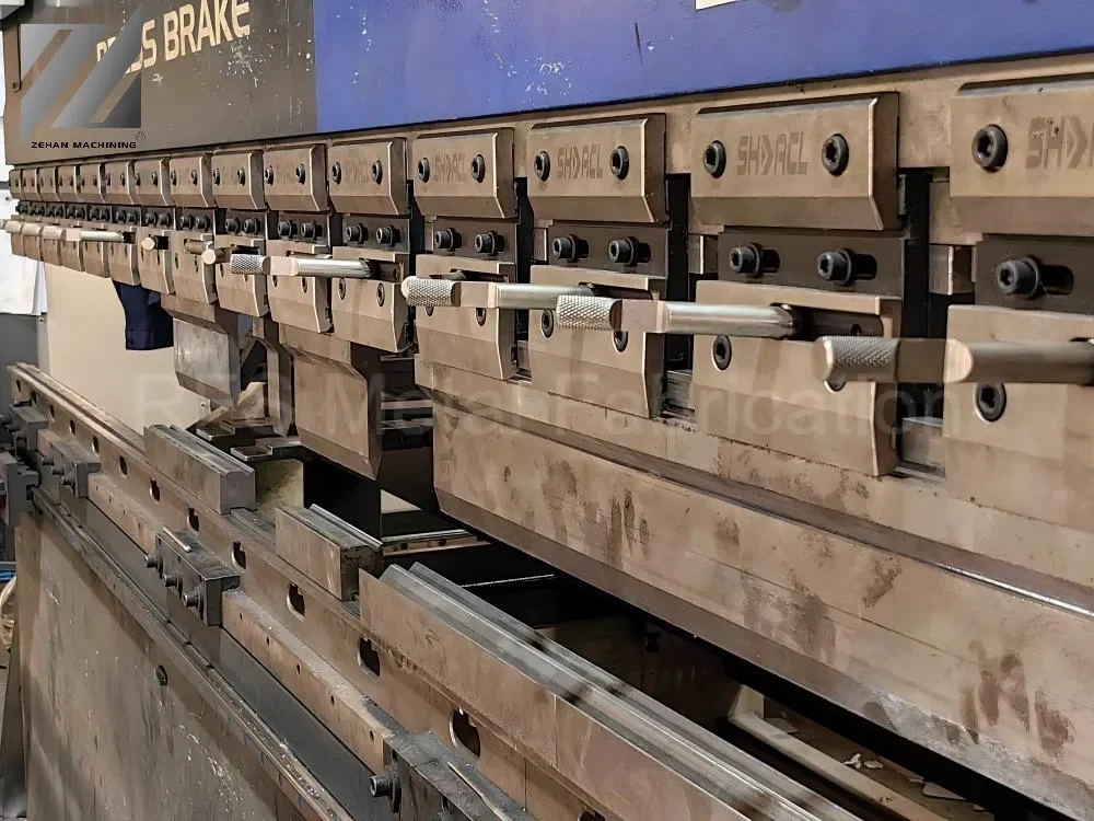
Sheet Metal Forming Services Capabilities
| SERVICE ITEMS | SPECIFICATIONS & CAPACITY | STANDARD TOLERANCE |
|---|---|---|
| Available Materials | Mild Steel, Stainless Steel, Aluminum, Brass, Copper, Galvanized Steel | Raw Material Standards |
| Material Thickness | 0.5mm – 6.0mm (Varies by material) | ± 0.05mm – ± 0.15mm |
| Max Part Dimensions | Up to 3000mm × 1500mm | ± 0.2mm – ± 0.5mm |
| Bending Angle | 30° – 180° Range | ± 0.5° (t < 3mm) / ± 1.0° (t ≥ 3mm) |
| Min. Bend Radius | 0.8t – 1.5t (Material Dependent) | ± 0.15mm |
| Min. Bending Flange | ≥ 3 × Material Thickness (3t) | ± 0.3mm |
| Hole Diameter | Minimum ≥ Material Thickness (1t) | ± 0.10mm |
| Hole to Edge Distance | Minimum ≥ 2 × Material Thickness (2t) | ± 0.15mm |
| Surface Finishing | Powder Coating, Anodizing, Plating, Brushing, Polishing | RAL / Pantone Standards |
| Compliance Standard | ISO 2768-m (Medium) | Industry General Standard |
* Note: The above parameters are for standard processing. For high-precision requirements or custom tolerances, please contact our engineering team for technical evaluation.


Common Materials & Forming Range
|
Material |
Thickness Range |
Min Bend Radius (≈) |
Common Forming Features |
Notes |
|
Mild Steel |
0.5 – 6.0 mm |
≥ 1.0 × thickness |
Bending, Flanging, Ribbed Bending |
Widest application, good stability |
|
Stainless Steel |
0.5 – 5.0 mm |
≥ 1.5 × thickness |
Bending, Stretching, Partial Forming |
Noticeable rebound, requires pre-set angle |
|
Aluminum |
0.5 – 4.0 mm |
≥ 1.0 × thickness |
Bending, Ribbed Bending, Simple Stretching |
Soft material, but easily scratched |
|
Galvanized Steel |
0.5 – 3.0 mm |
≥ 1.0 × thickness |
Bending, Flanging |
Surface coating needs protection |
|
Copper / Brass |
0.5 – 3.0 mm |
≥ 0.8 × thickness |
Complex Bending, Forming |
Good ductility, suitable for complex structures |
Some designs may seem easy on paper, but in actual production, they may be affected by materials and thickness. For example, a too-small bending radius or excessive local deformation may occur. It’s necessary to allow some leeway in the early stages.
When RFS receives the drawings, it usually takes a quick look at these details. If we find they are obviously difficult to shape, we will confirm with the customer in advance to avoid making modifications during production.
Applications of Sheet Metal Forming

Shell Components
Many shells are initially flat sheets. They are gradually transformed into three-dimensional structures through bending. Edges are usually left to make them easier to secure during assembly and to prevent wobbling.
When making these types of parts, RFS focuses on perfecting the edges and corners. As long as the dimensions are stable, assembly is generally not a major issue.

Bracket Structures
Simply cutting out a bracket would result in a rather soft structure. Therefore, an edge is usually added, or it is simply pressed to make it more rigid.
When making these types of parts, RFS avoids overly complex structures, focusing on functionality and stability.

Enclosures and Cabinets
Enclosures are typically formed by bending rather than being molded from a single piece of material. Its various sides must be connected to each other through a bending process; otherwise, the overall structure will be loose and unstable.
When manufacturing such products, RFS strictly controls the precision of the bending positions. This ensures a smoother assembly process and eliminates the hassle of frequent calibration and adjustment.

Parts with Mounting Points
Some components have additional fine structural features, such as folds or small protrusions. These features facilitate fixing with screws.
When RFS handles these areas, they generally consider actual usage, not just following the drawings.

Large-area Reinforcement Structures
When the board area is relatively large, a rib is usually added. It may not look like a big difference, but you can feel the difference by touch; it makes the board much stiffer.
When RFS makes this type of structure, they consider the board thickness to determine the appropriate depth, avoiding excessive depth. The key is to make it just right for the intended use.